¶ How To Use Solidworks CAM
Hi! Theresia here. This page is still in progress. Thank you for your patience!
¶ Requirements
You must read this section before continuing.
- The part must be manufactured in MMGS units.
- Each file can only have one tool or orientation. Any different tool or orientation must be a different file. Attempting to run a file with multiple tools or orientations will at best not run and at worse fatally damage the machine and stock material.
- Do not use "Generate Operation Plan". This is due to rule 1, as it will use lots of different tools and orientations. While you can decide to change all of the tools and planes individually you will likely end up wasting more time than if you made the toolpaths yourself.
¶ Frequently Asked Questions
| Question | Answer |
|---|---|
| How do I change a tool? | Right click on the toolpath you want to change. |
¶ Common Errors
If you have an error not listed below and have not been able to find the solution elsewhere, email us at meen3dprinting@tamu.edu with the subject line 'Solidworks CAM Error Help Requested' with a description and screenshot of the issue. and we will get back to you as soon as possible, and also add it to this wiki.
| Issue | Cause | Fix |
|---|---|---|
| Toolpath not running in preview | The tool is too big for the toolpath. | Change the tool or toolpath size. For which one to change will depend on your design. The easiest is to change the toolpath size since you'll need a new file for the new tool. |
¶ Warning Symbols & Their Meanings
If you have a warning not listed below and have not been able to find the solution elsewhere, email us at meen3dprinting@tamu.edu with the subject line 'Solidworks CAM Error Help Requested' with a description and screenshot of the issue. and we will get back to you as soon as possible, and also add it to this wiki.
¶ Small Icon Warnings
| Symbol | Meaning | Fix |
|---|---|---|
 |
Non-Fatal error on the feature | The feature will tell you what is the issue.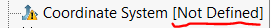 Right click on the 'What's Wrong?', it will explain what the issue is and provide guidance on how to fix it. Solidworks posts excellent documentation. Or, googling it is a good idea as well. 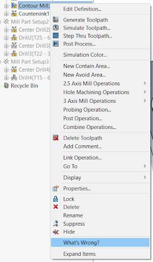 |
¶ Larger Warnings
| Message | Meaning | Fix |
|---|---|---|
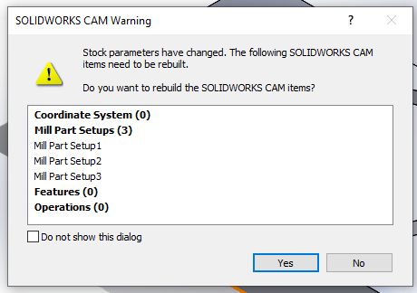 |
Every time the stock is changed SolidWorks wants to rebuild everything | It's generally okay to always let SolidWorks rebuild if it wants to, click 'Yes'. |
¶ Quick-Start Guide
If you already have experience with CNC machining, this is a quick guide from opening Solidworks CAM all the way to Processing. This will give you all of the information on how to do it without going too in depth. If you need more informaition, there will be more below.
- Make part in Solidworks. Exporting from Fusion or other softwares also works, but in general Solidworks CAM handles Solidworks files the best.
- Open Solidworks CAM
- Define Machine.
- Metric Mill with light duty
- FADALCNC with Post Processor
- Define Stock Manager
- 316S for Aluminum
- Monel Alloy K500 for harder materials
- Define Coordinate System
Tip: Define your coordinate system in the top left or right
- Extract Machinable Features / Create Your Features
- Create 2.5 Axis Mill Operations by Right-Clicking on one of the Mill Setups
- Pick your tool:
- Rough Mill: 2mm, 4mm, 6mm
- Contouring/Engraving
- Currently we do not stock any other tooling, if you need other tools, please bring it in
- Pick your tool:
- Generate the Toolpaths and Simulate the Toolpaths, ensure they look correct
- Post Process the Gcode
- Save as '.cnc'
- Open in Solidworks CAM NC
- Remove any 'Z0 H0 M05'
- Save onto flash drive
- Put Gcode on machine
- Plug in flash drive
- Select Page
- Enter
- Verify file name is on top.
- Zero the machine
- Hit reset if the machine is blinking
- Secure part to machining bed/surface
- Place the origin/zero at the same part as in your Solidworks part
- Zero X and Y axis
- Use MPG to move the X and Y axis
- Zero Axis
- 2ND
- X or Y Zero
- X or Y Axis
- Enter
- Zero Z Axis
1. Lay puck on top of part, same Z plane as origin
2. Attach clamp to tool
3. Move Z Axis down flightly using MPG, make sure it is close to touching but not exactly, a good reference is ~1 cm away
4. 2ND
5. Probe Twice
- Start running file by hitting green start putting on the bottom left
¶ In-Depth Guide
¶ Before Opening Solidworks CAM
- Create your part in Solidworks with the MMGS units. Our mills are using MMGS, this is a requirement.
- Determine which tool and orientation this file will be. You can only use one tool and one orientation per file, this is a requirement.
- Create geometry that makes sense and would be able to be manufactured. Ex: Avoid very thin geometries that could be broken off.
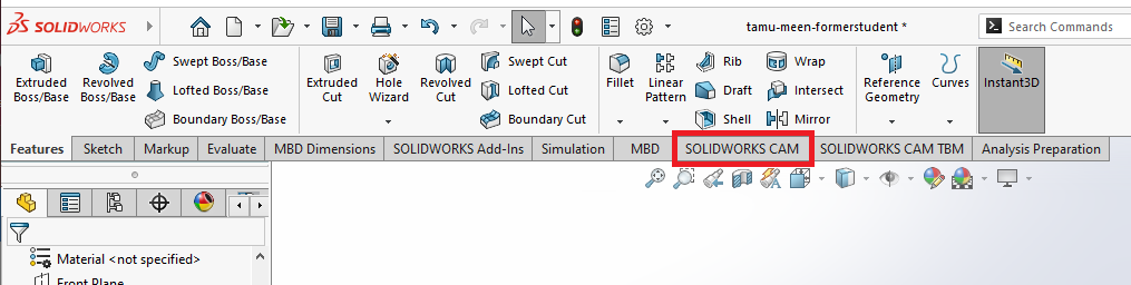
¶ Open Solidworks CAM
In the main ribbionm, towards the right there will be 'Solidworks CAM' as an option. Click on that.
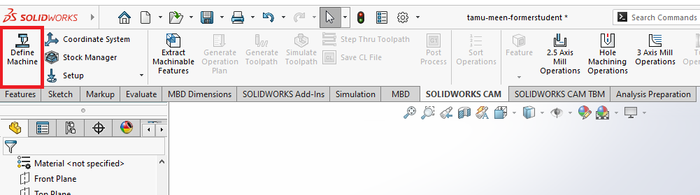
¶ Define Machine
Click 'Define Machine' in the top left.
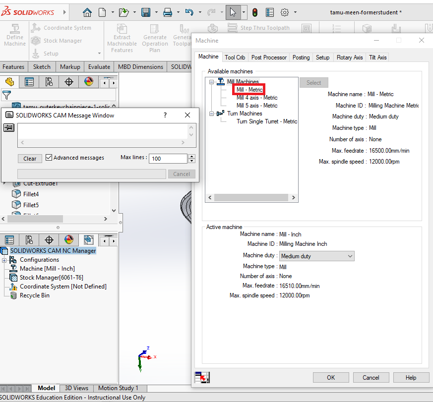
Select 'Mill - Metric'. All our CNC machines are that.
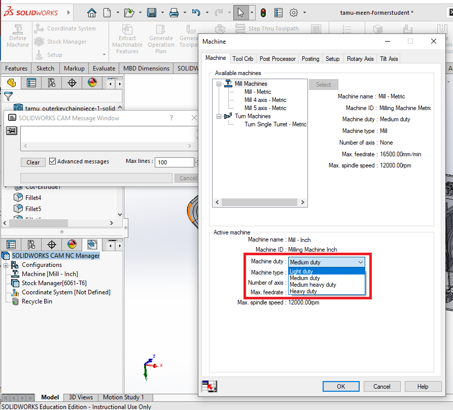
Select 'Light Duty'. The CNC machine is not super strong, and therefore we need lower spindle speeds.
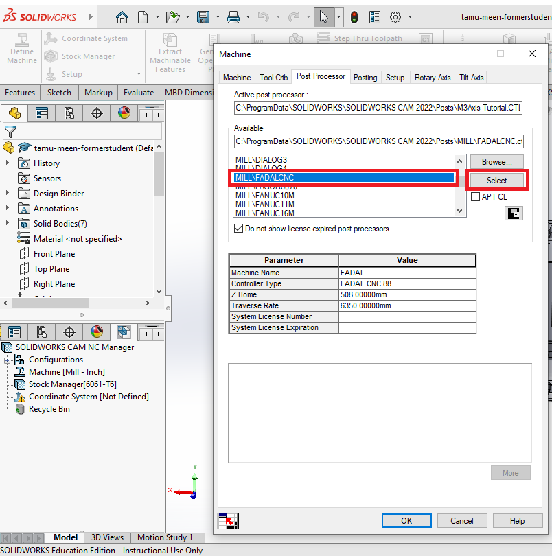
Click 'Post Processor' in the machine ribbion.
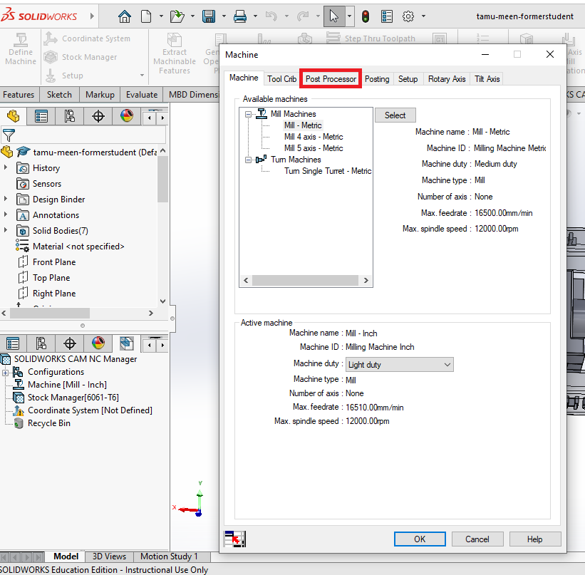
Scroll to select 'MILL\FADALCNC', then click 'OK'
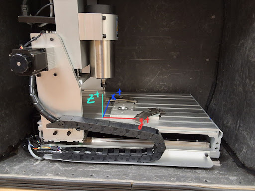
¶ Define Coordinate System
First before defining the coordinate system, take a moment to think where exactly you would want the origin of your part to be. It is standard to select a top surface on a corner.
Our smaller sized CNC machine has the following coordinate system, ensure your part follows the same orientation.
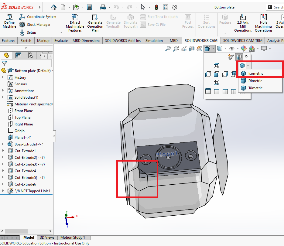
¶ Putting in Isometric View
Hit CTRL+7 or the 'View Orientation' button underneath the main ribbon to put the part in isometric view.
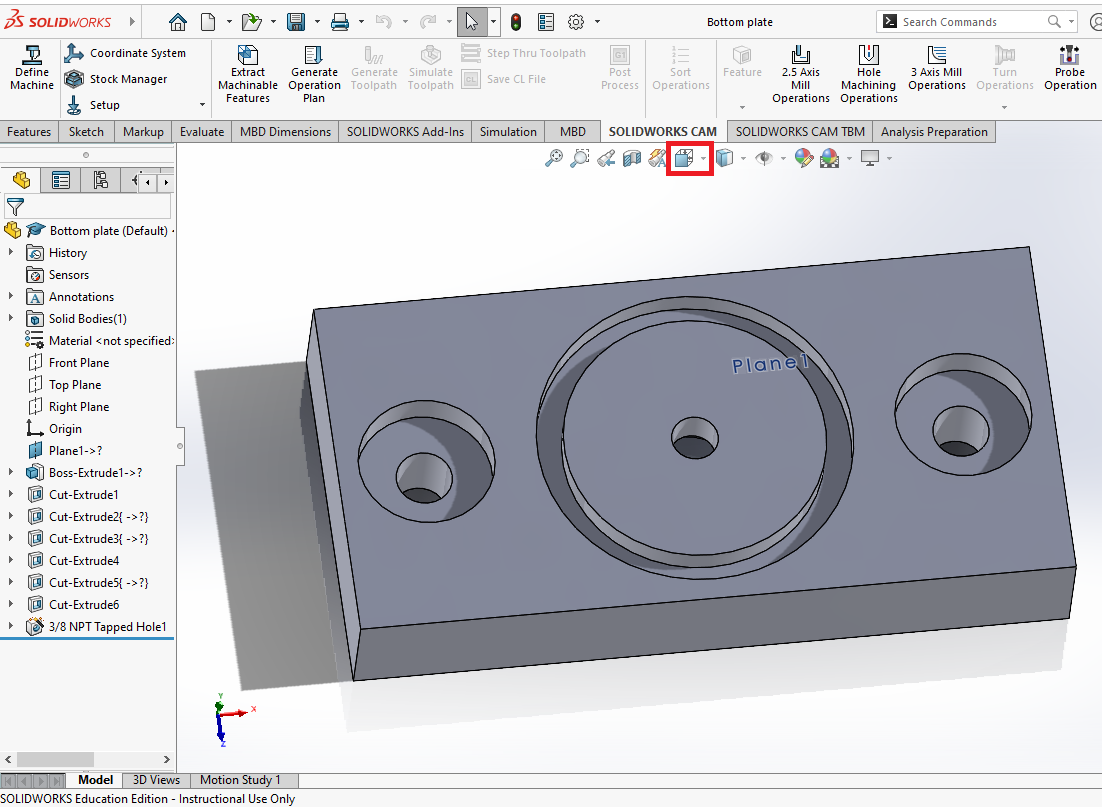
Assuming you did the latter, click on the drop down of the fully colored cube to select Isometric or select one of the top corners of the view.
¶ Setup
Click 'Coordinate System' in the top left.
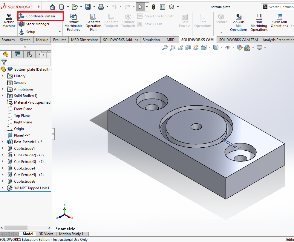
Set up the coordinate system:
- Under Method select 'User Defined'
- Select 'Part Bounding Box Vertex' or 'Stock Bounding Box Vertex'. Considering your part is made up of the same stock material, they are interchangable.
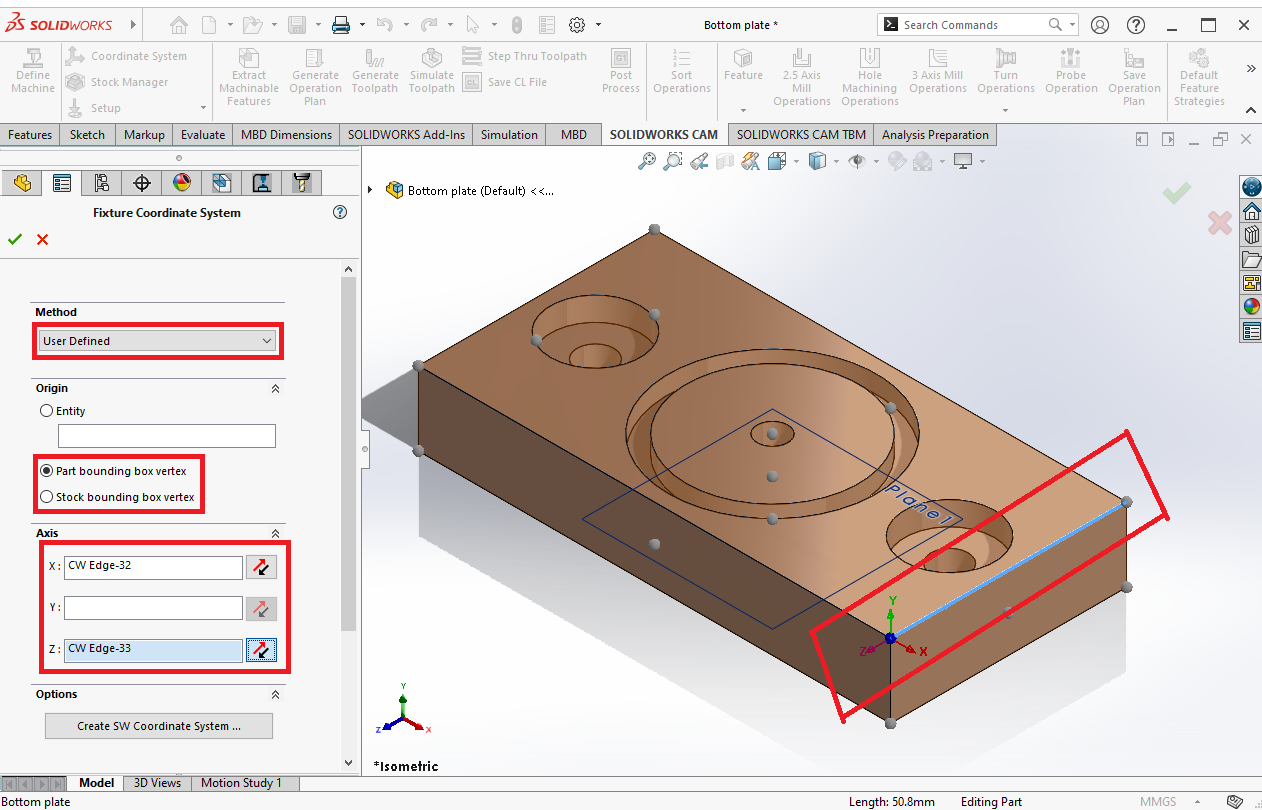
- Define your axis in one of the following ways. As a suggestion, first go with using a dot on the top surface and if that doesn't give you what you want, use the axes and refine.
- Clicking on one of the given dots. Easier but less specific.
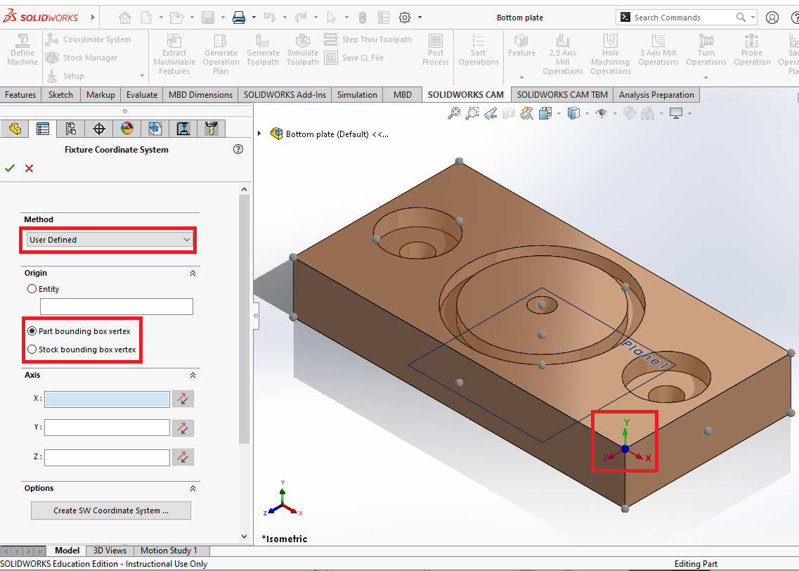
- Using the axes. Little more complicated, but it allows you to better define which way is positive along the axes.
- Clicking on one of the given dots. Easier but less specific.
Ensure that the Z is set somewhere along the top face, and set the x/y axes along a corner of your part.
¶ Define Stock Manager
Click 'Stock Manager' in the top left.
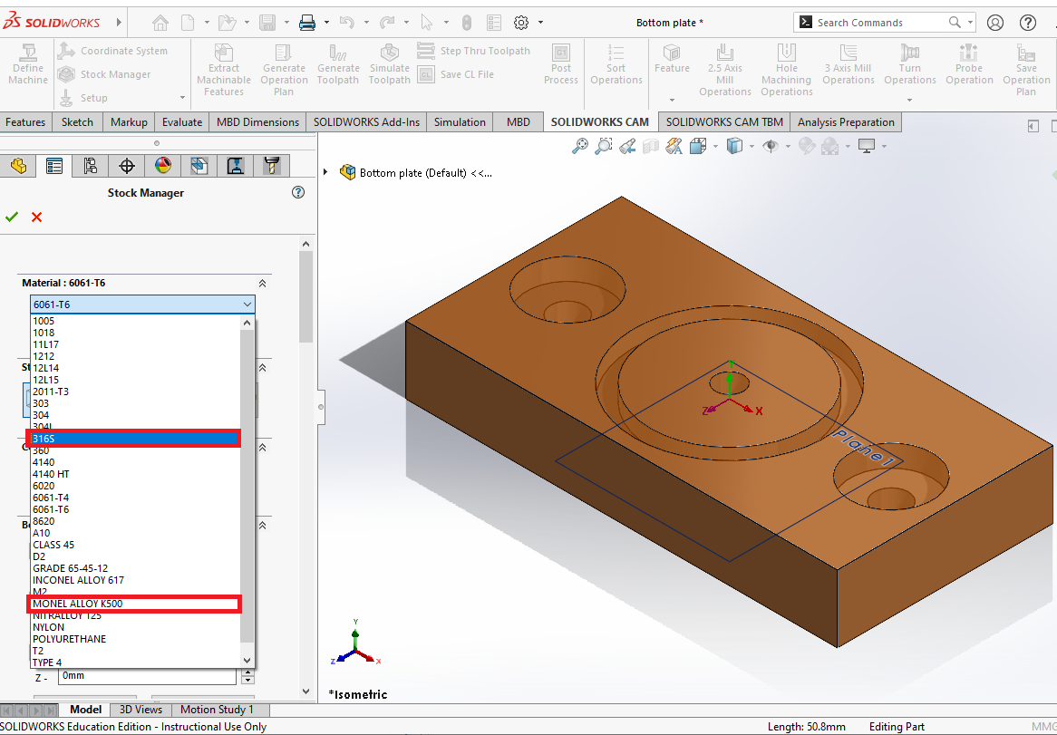
Click the dropdown that has a material name on it.
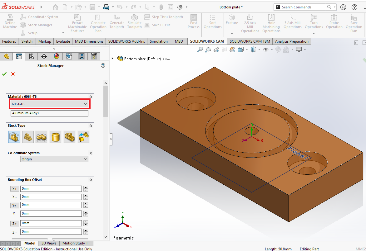
If cutting alumnimum select 316S, if cutting steel or harder materials select an alloy (my favorite is Monel Alloy K500)
¶ Create Machinable Features with Extract Machineable Features
There are two methods to create your machineable features. The recommendation is to first start with 'Extract Machineable Features', and if they don't generate correctly, to make your own 2.5 Axis Mill features.
Click 'Extract Machineable Features' in the top left.
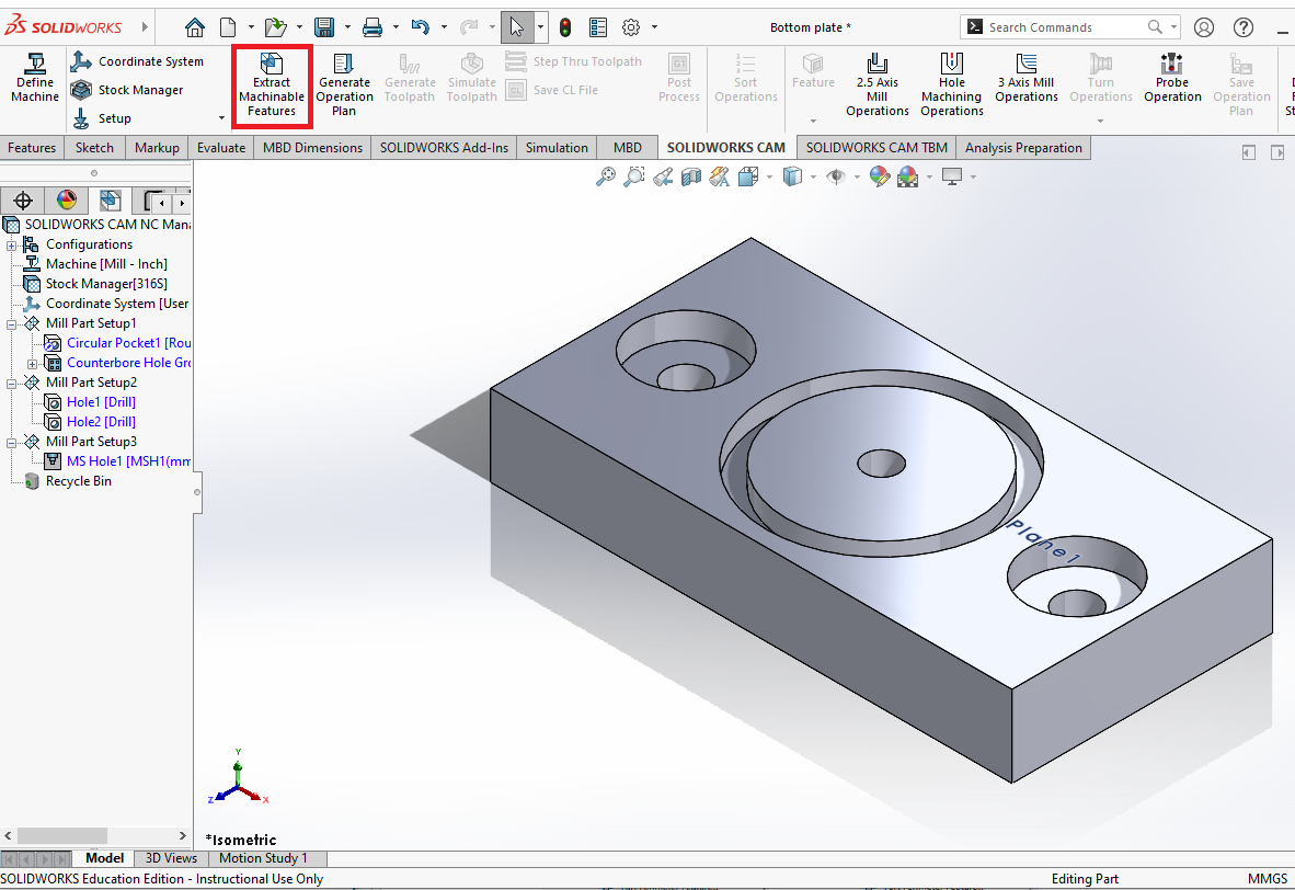
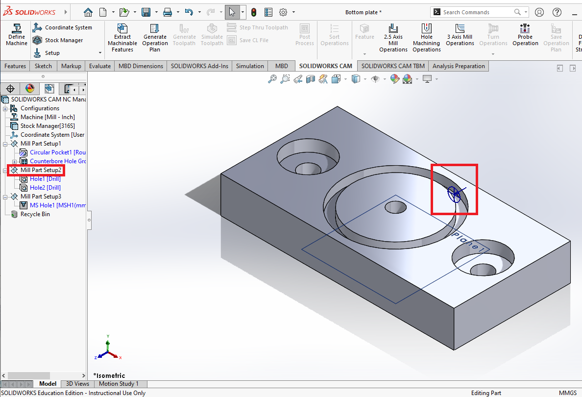
Check Solidworks CAM Feature Tree and verify that it is correctly extracted all of the parts you need.
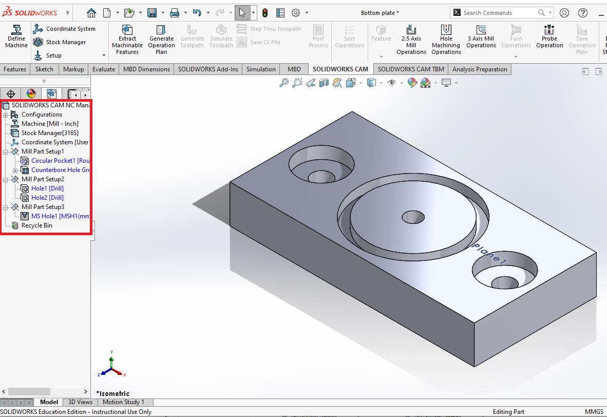
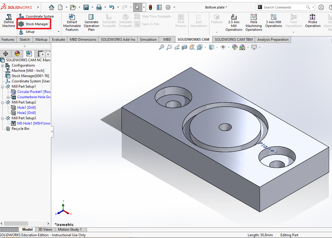
Suppress the Mill Part Setups you do not intend to use in the file, or delete them in you plan to never do them. You can hover over the text that says 'Mill Part Setup' to see exactly which face they are machining on. Use this to check which setup you want this file to use.
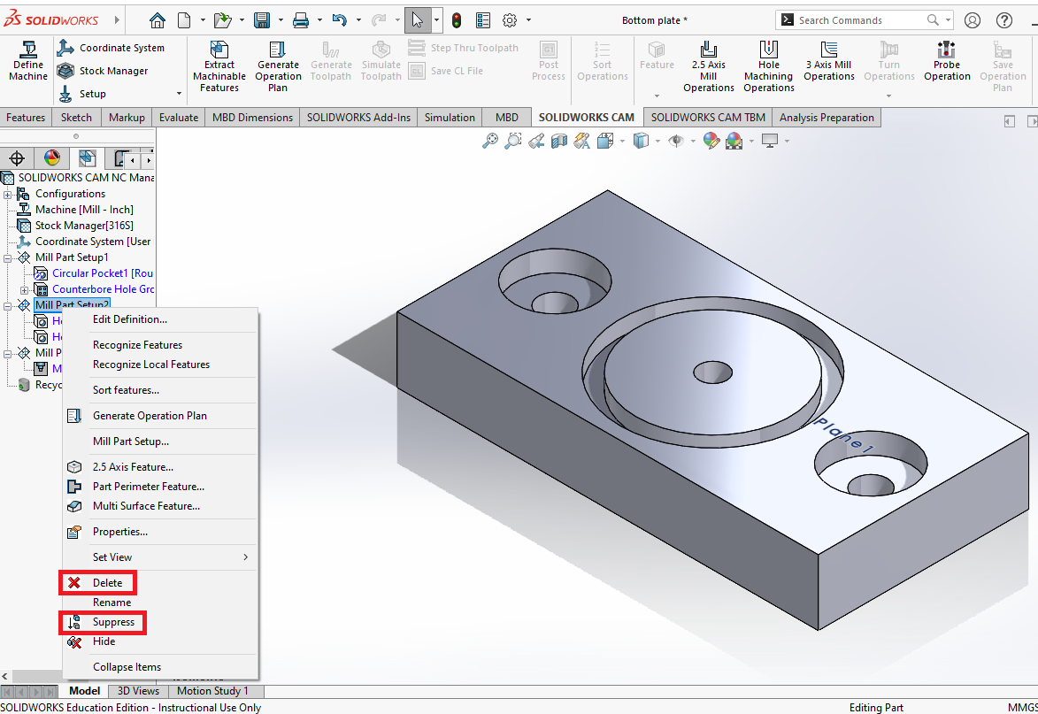
Suppress or delete the Mill Part Setups by right clicking on the 'Mill Part Setup', and selecting either the 'Suppress' or 'Delete' button. In rare cases Solidworks can be finicky and can generate errors on a suppressed setup even if it shouldn't, in that case you can always delete it and on your next file just extract the machinable features again.
Reminder: Only one orientation per file.
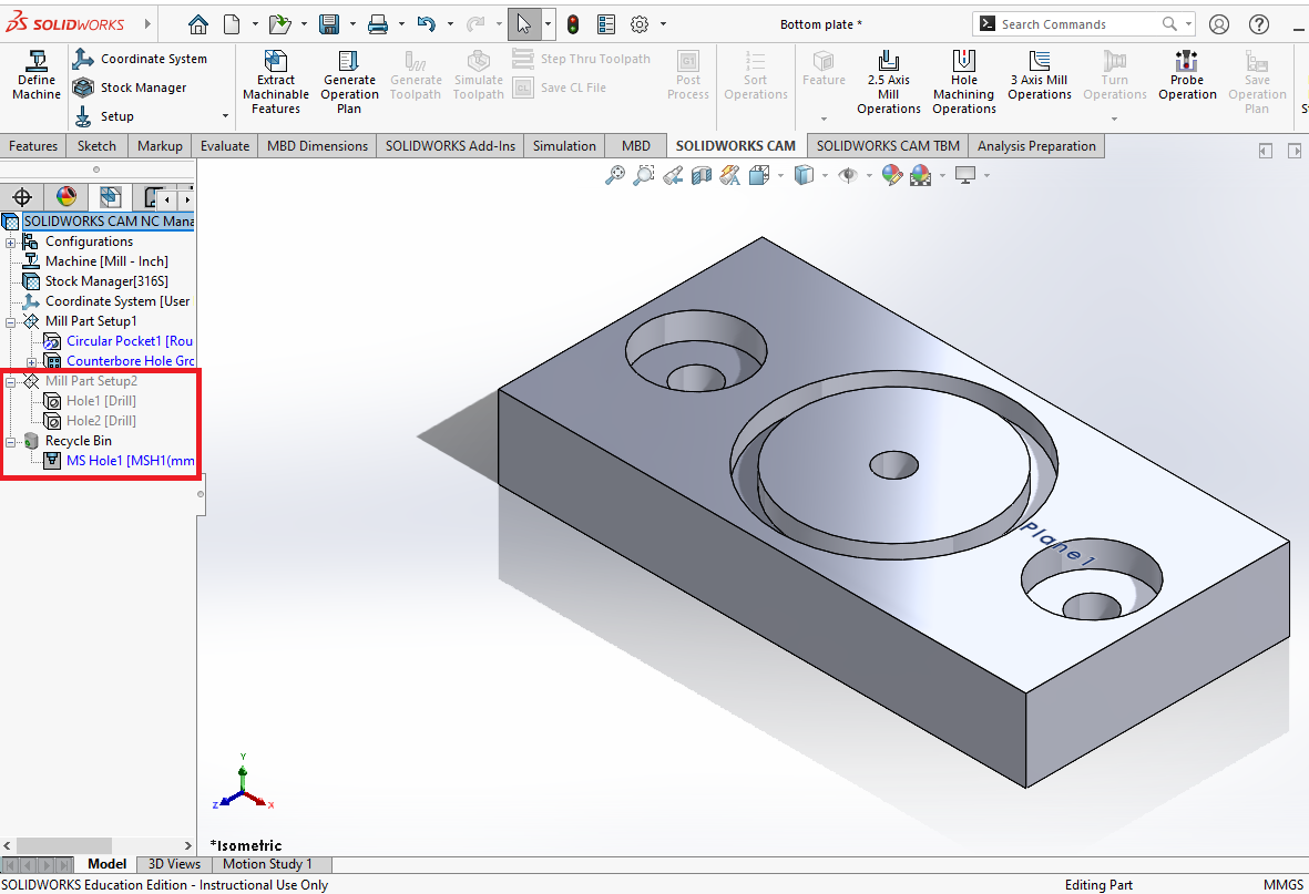
This is the result after supressing and deleting setups I do not intend to use. Ensure your suppressed ones are fully greyed out, and that your deleted ones are in the recycling bin.
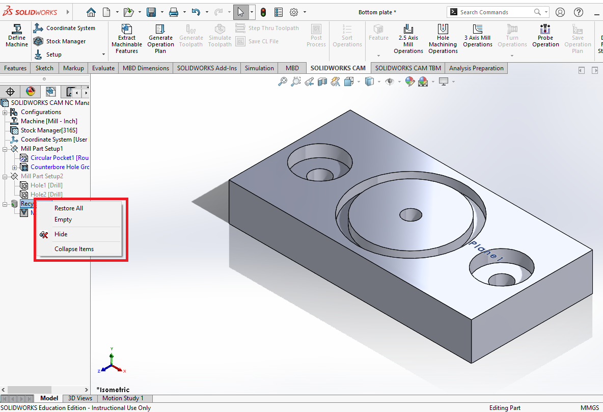
For the deleted setups, you can either empty the recycling bin now or right before post-processing. The option to empty, and also to restore if you accidentally deleted the wrong one, can be found by right clicking on the 'Recycle Bin'.
¶ Create Machineable Features with 2.5 Axis Mill Features
If 'Extract Machineable Features' worked correctly, this section can be skipped, however knowing how to create your own features is very beneficial as well.
Right-click on the 'Mill Part Setup' and click '2.5 Axis Feature'.
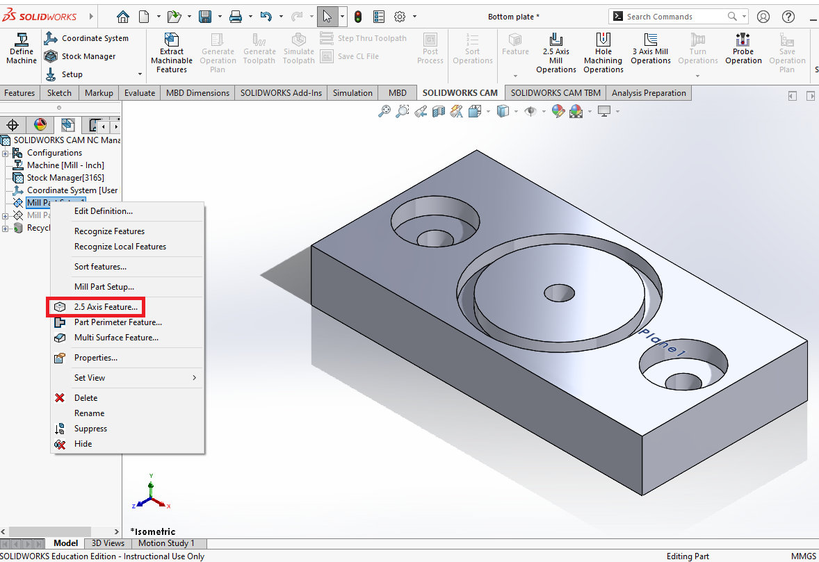
Select the type of feature it is, and define it with edges/sketches/faces. There are 10 features to pick from.
| Feature | Picture | Use When | Defined By | Allowed Operations |
|---|---|---|---|---|
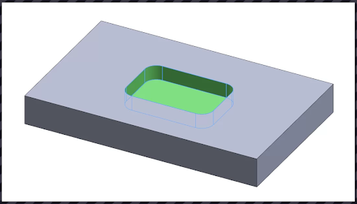 |
You need a recessed area in a part where none of the sides are open to the air | Sketch, face, edges parallel to the current mill part setup. Perimeter must be a closed non self-intersecting loop | Rough Mill, Contour Mill, Thread Mill, and all Hole Machining Operations | |
| Open Pocket | 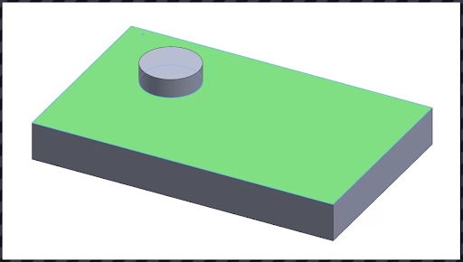 |
You need an area open on all sides and extends beyond the rest of the part | Sketch, face, edges parallel to the current mill part setup. Perimeter must be a closed non self-intersecting loop | Rough Mill, Contour Mill |
| Slot | 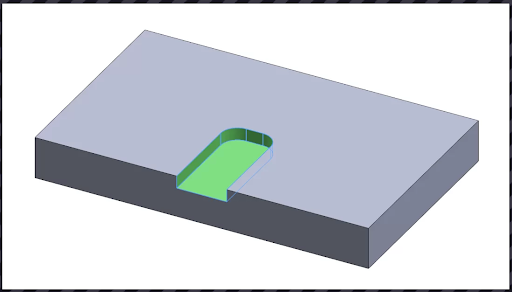 |
You need an area that has one side of the part open | Sketch, face, edges parallel to the current mill part setup. Perimeter must be a closed non self-intersecting loop | Rough Mill, Contour Mill |
| Corner Slot | 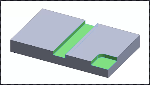 |
You need an area that has two sides of the part open | Sketch, face, edges parallel to the current mill part setup. Perimeter must be a closed non self-intersecting loop | Rough Mill, Contour Mill |
| Boss | 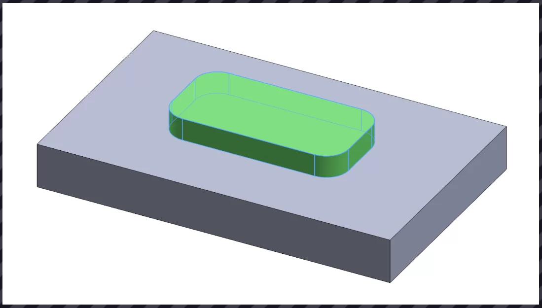 |
You need a raised area of material to cut around, only cuts around the extrude | Sketch, face, edges parallel to the current mill part setup. Perimeter must be a closed non self-intersecting loop | Rough Mill, Contour Mill |
| Hole | 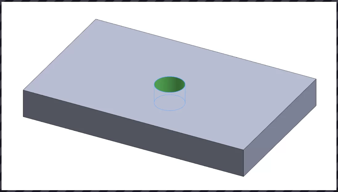 |
You need a round profile that cuts part of or through a part | Sketch, face, edges parallel to the current mill part setup. Perimeter must be completely circular | Rough Mill, Contour Mill |
| Open Profile | 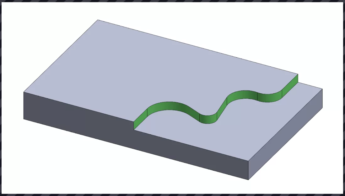 |
You need to make a cut where the start and end are different (i.e. alongside the edge of a part) | Sketches or edges parallel to the current mill part setup. Perimeter must be opened and non self-intersecting | Contour Mill |
| Engrave Feature | 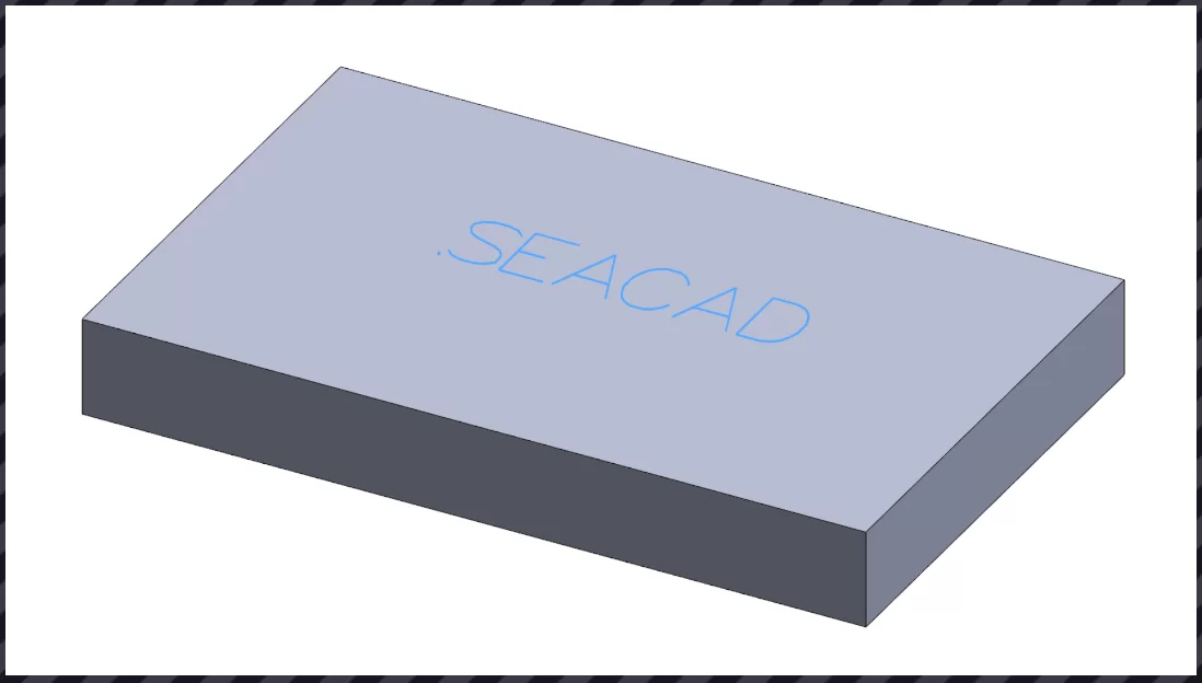 |
You need to engrave something, toolpath can’t be offset | Sketches (lines, arcs, splines, and text objects), faces, or edges parallel to the current mill part setup. Perimeter must be open or closed and self-intersecting | Contour Mill |
| Curve Feature | 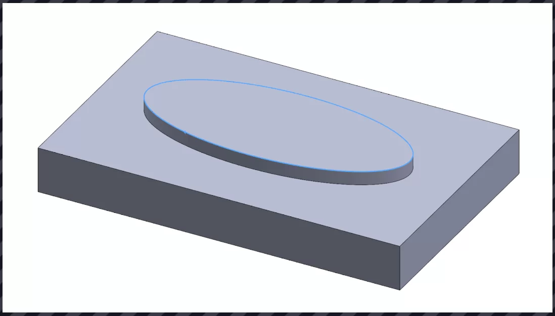 |
You have chamfers or want the tool to follow a 2D or 3D sketch | 2D or 3D sketches, faces, or edges. Perimeter must be open or closed and self-intersecting | Contour Mill |
| Face Feature | 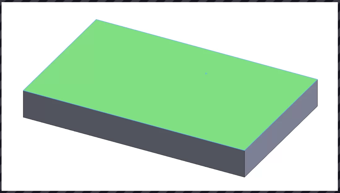 |
You want to machine the top of the face (such as making it all flat) | Sketch, face, edges parallel to the current mill part setup. Perimeter must be a closed non self-intersecting loop | Rough Mill, Contour Mill |