¶ Exporting 2D Files From Solidworks
If images are hard to read due to pixelization, it may be due to browser compression. Click/press on the image to see a full screen image.
¶ Motivation:
3D printing takes a 3D part file as input into your slicer (usually an STL). You need that third dimension of data to specify what your part looks like. 2D subtractive methods such as Laser Cutting, Waterjet Cutting, CNC Routering, and Plasma torch cutting do not (typically) need a third dimension from your part file. Instead, the third dimension of your part is specified with your stock material. Whatever the thickness of your material, that will be the thickness of the finished part. You will need to specify this thickness to your CAM software, but you can't tell the software to change this thickness.
Beause different data is needed, a different file type is needed too. This is usually a DXF or SVG file. This article will walk you through exporting a DXF from Solidworks and will discuss the basic ideas when designing for these manufacturing methods.
¶ Relevant Manufacturing Methods:
- CNC Routering
- Waterjet cutting
- Laser Cutting
- Plasma Cutting
¶ Basic Part Design:
When designing a part for these manufacturing methods, you should be able to complete the entire part (component) in 1 sketch and 1 boss extrude (except for very special cases). This is because the machine can really only trace on a plane, like a standard sketch, and your material selection is almost certainly just a piece of sheet stock.
Because you will want to use your part/component in a Solidworks assembly to check that everything lines up and looks as expected, the following process is how you will typically model a part:
¶ Basic Modeling Process:
- Create a planar sketch that contains all of the details you want on your part.
- Extrude your sketch to the thickness of your material. Now you have an object that should be very close to the product of these manufacturing methods. You can use this model in your assemblies to verify fit and function.
¶ Exporting the DXF:
Now that you have your part, we can export the DXF.
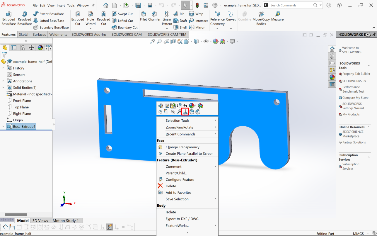
First, go normal to the cut plane by right clicking on the cut face and selecting the normal view:
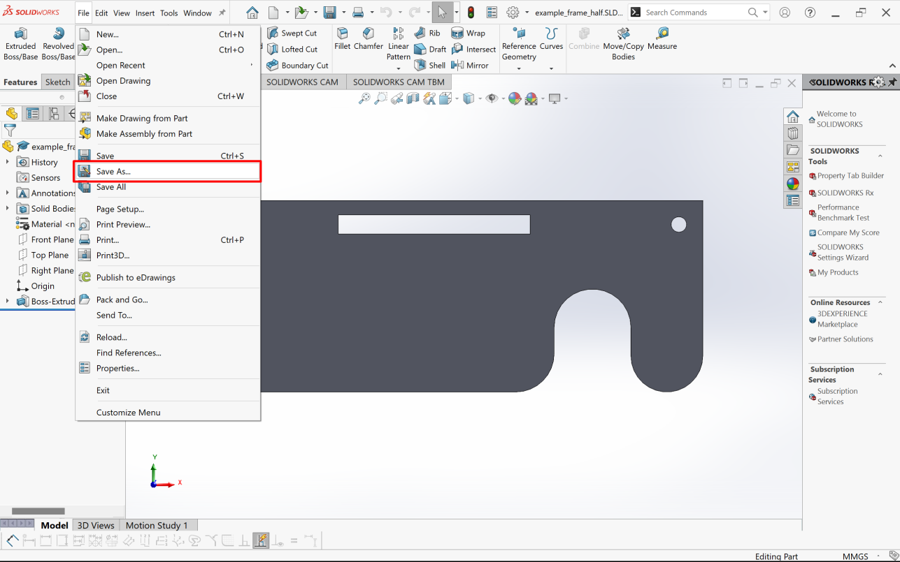
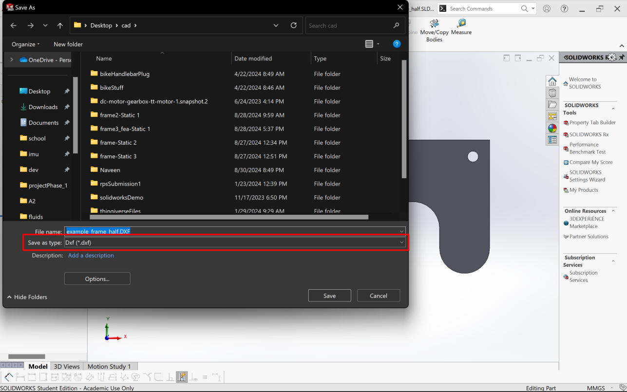
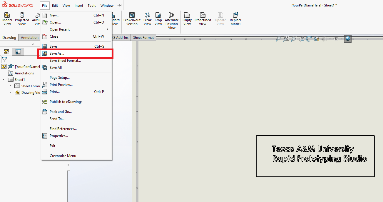
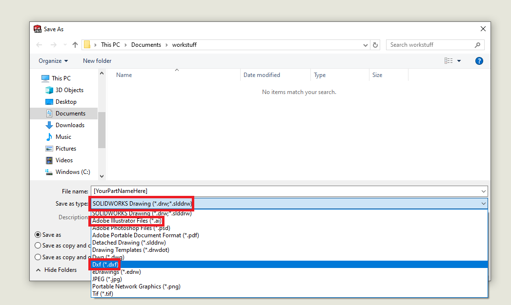
Once you are in the normal view, go to "File">"Save as" and change the output type to .dxf.
This will bring you to a view selection menu. Since we selected normal to the surface, we can leave the "Views To Export" option as "*Current". We could select one of the sketch planes here instead, if we knew which perspective we wanted. Cick "Ok" to continue.
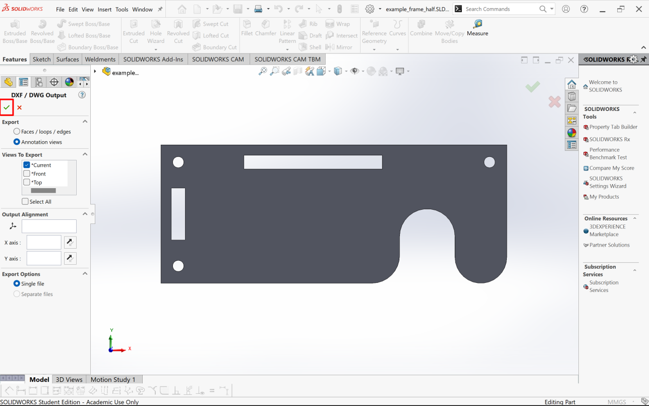
Solidworks will now generate a view of the DXF. You should see the outline of your part. You should not see any lines showing depth, this should be a planar projection of your part. You also should not see any dimensions. If this view looks correct, select "Save" to save your part.
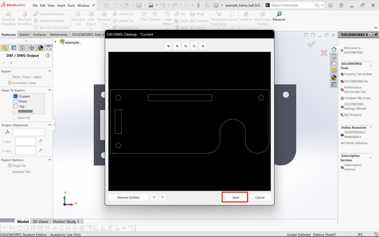
When loading a DXF into a piece of CAM software, you should always verify that the imported file matches the expected size. The prescribed method appears to work correctly for more modern pieces of software, but dated CAM software is EXTREMELY common in industry. Always use a scale in your CAM software to double check the size.
¶ Another Way: Exporting DXFs from Drawings
¶ Creating New Drawing File
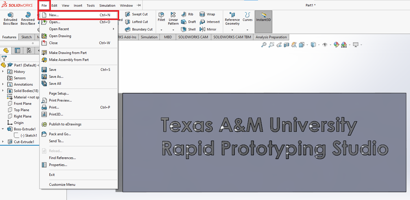
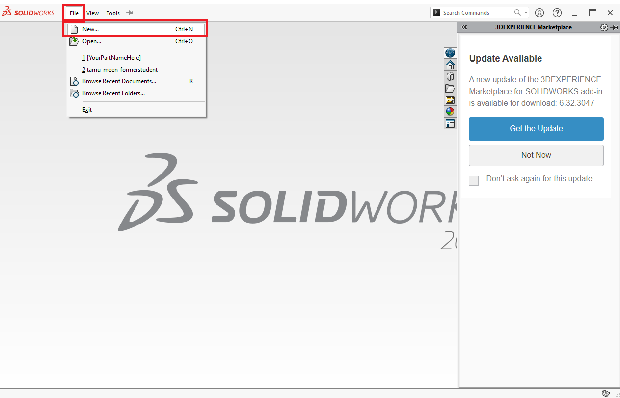
Hovering over the top left "SOLIDWORKS" text will reveal the standard "file/edit/view/insert/tools/window" ribbon. In the 'File' window, find the 'New' ribbon and select.
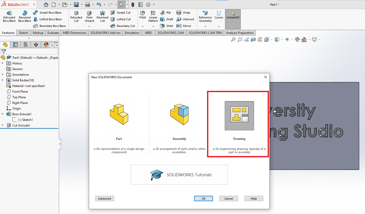
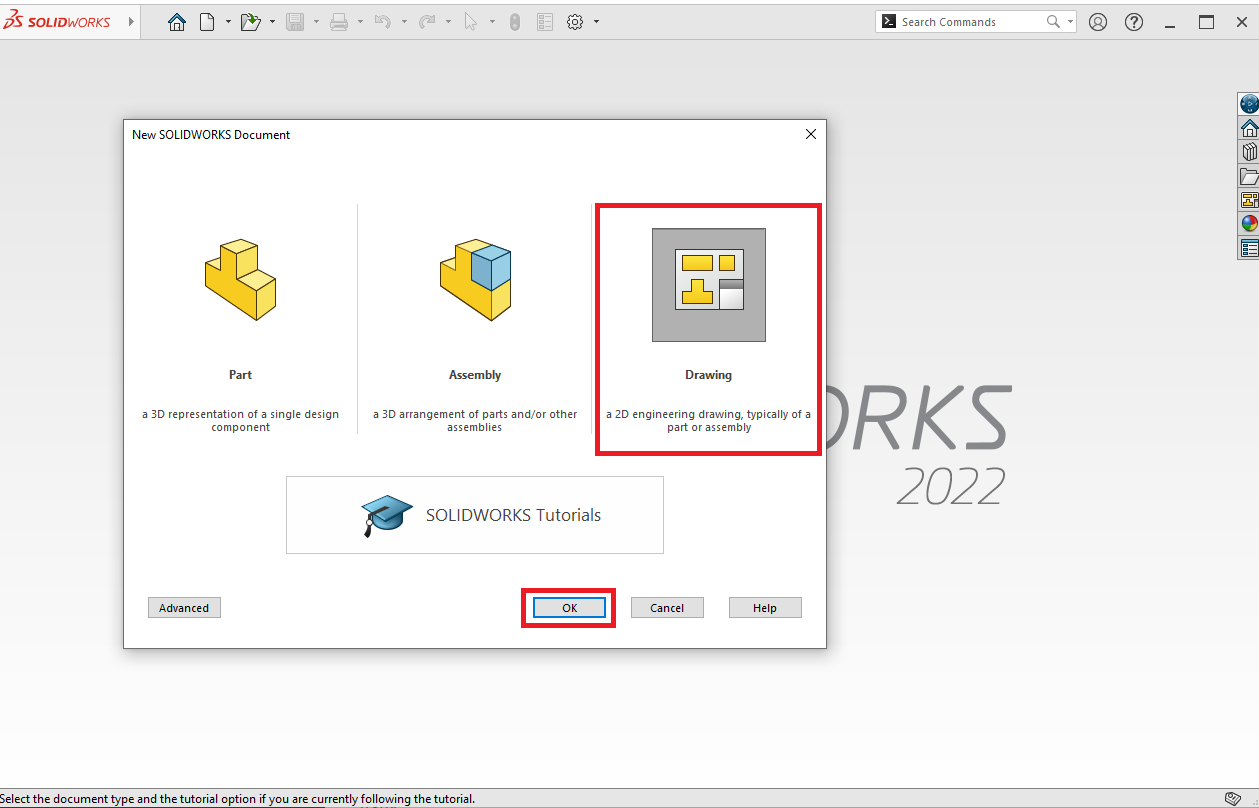
It will open a menu for you to choose which kind of file to create. Click on the Solidworks Drawing icon and click 'Ok'.
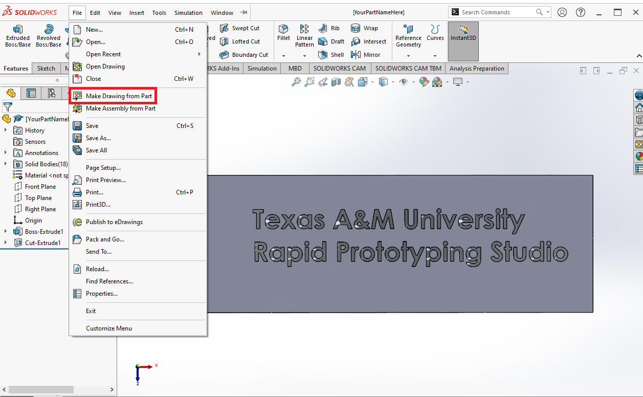
Alternatively, you can click 'Make Drawing From Part', but the aformentioned method is still good to know.
¶ Picking Drawing Sheet Size
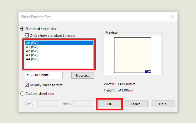
Once the drawing opens, a menu will appear in the middle of the screen asking for the size page you want to create. It is best to pick a standard sheet size, and different projects will require a different size. The closest to a typical sheet of paper is A4. You will notice this guide uses the A0 sheet size, however it is apartent that a different sheet size would have fit the task better.
Standard Dimensions for ISO A Series Sheets:
| Sheet | Metric Dimensions | English Dimensions |
|---|---|---|
| A0 | 841 mm x 1,189 mm | 33.11 in. x 46.81 in. |
| A1 | 594 mm x 841 mm | 23.39 in. x 33.11 in. |
| A2 | 420 mm x 594 mm | 16.54 in. x 23.39 in. in. |
| A3 | 297 mm x 420 mm | 11.69 in. x 16.54 in. in. |
| A4 | 210 mm x 297 mm | 8.27 in. x 11.69 in. |
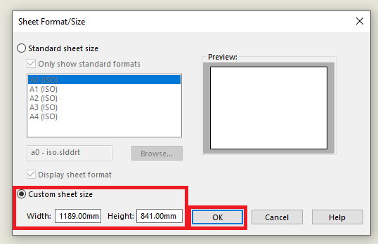
However, you can also do a custom sheet size by clicking the circle next to the Custom Sheet Size and entering the dimensions you would like.
It is important to pick the right sheet size for your project. Drawings will have a scale factor, and you do not want to have too large/small of a scale for both visual appeal and for manufacturing. The decision of course is not final, and you are able to change it later if needed.
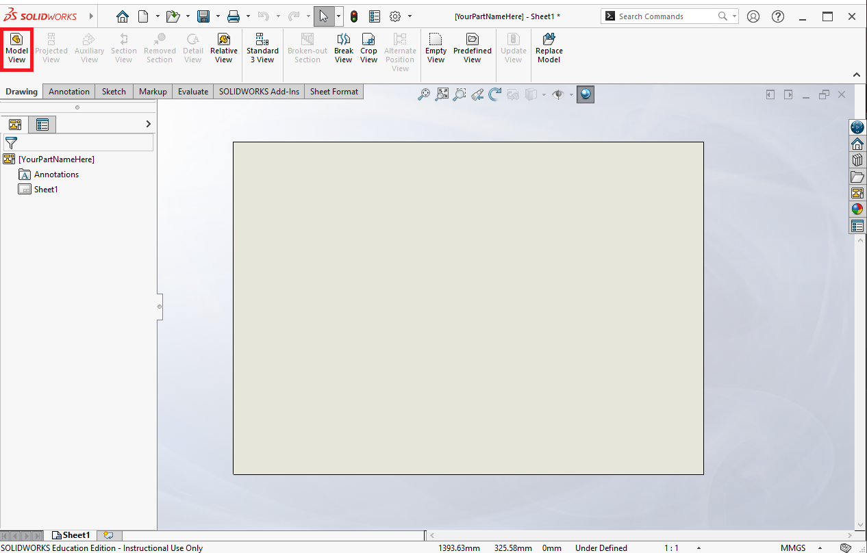
¶ Opening Model View
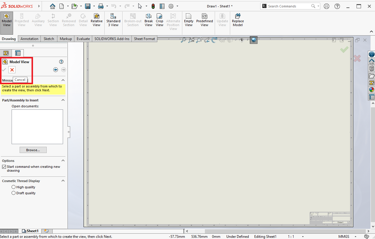
After clicking 'Ok', the sheet will open in Model View. Look to the left side of the screen. There will be two options depending on whether or not if the 3D part is already open.
¶ No Model View Shown?
If in the rare case the Model View does not open by default, it is possible to find the Model View in the top left of the screen.
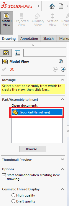
¶ Case 1: Part Already Open
If you already have the part open on your machine either by using the 'Make Drawing From Part' ribbon or other methods, the part will be shown in the 'Open Documents' box.
¶ Case 2: Part Not Open
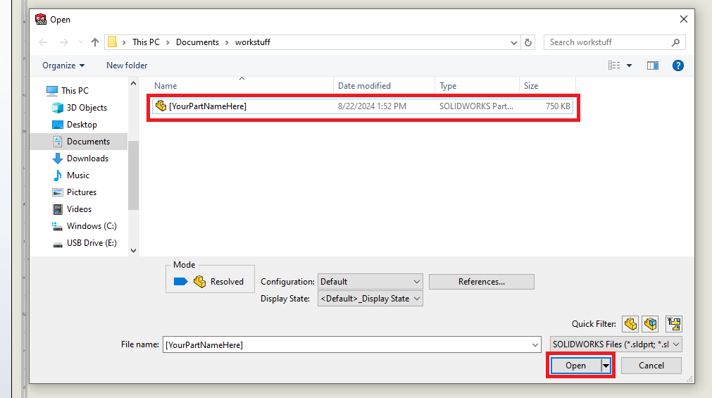
If there is no Solidworks part open, likely from creating a drawing upon opening the software, you will have to browse for the part.
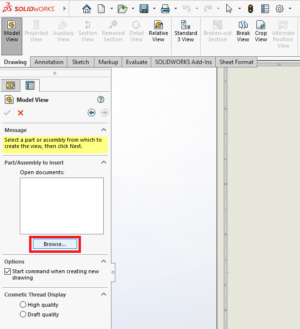
After clicking browse, select the part file and click open.
¶ Creating Model Views
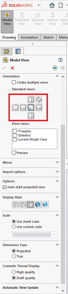
Next, on the left side of the screen you will be able to create 2D views of the 3D part. There are a lot of options on this menu, and as you get more experienced with creating drawings, it is very useful (and even fun!) to make more complicated drawings of a part. For now, we will stick to the standard views of the product. Since this is written in mind for planar manufacturing, you are only cutting from one plane/surface at a time.
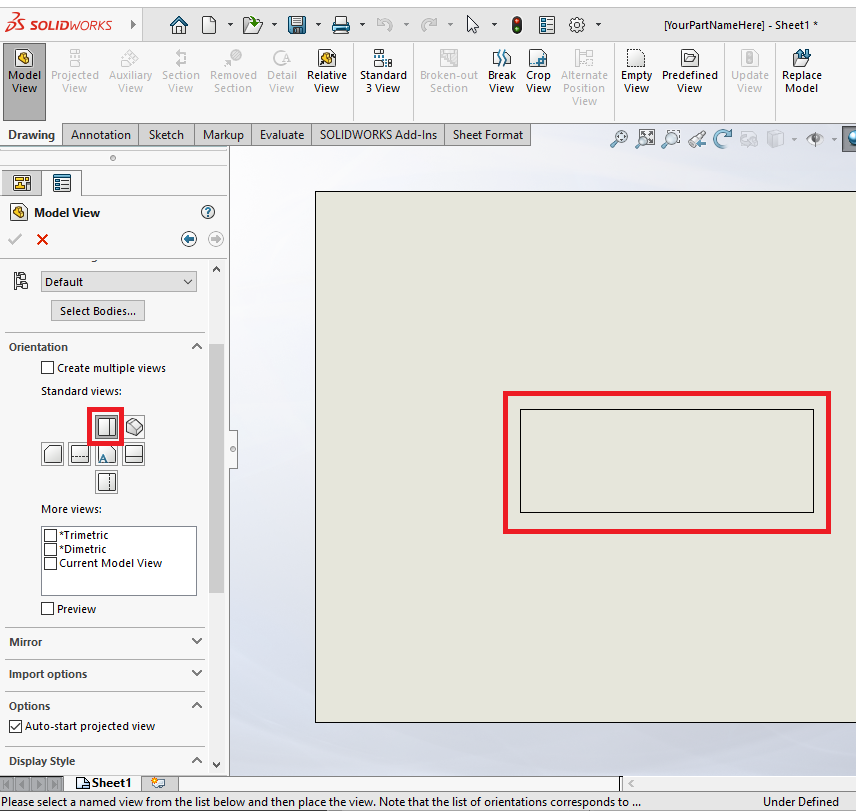
Boxed below are the standard views. Depending on how you created the part, the plane you want to cut will be any one of the options. You can see which view you need to use based on the right side of the screen, it will show a basic outline of what the part will look like.
In the case of this specific part, the view we actually want is not the automatic view.
The automatic view in the center shows a side profile of our part. The primary reason for this is which plane you sketch on when creating your part.
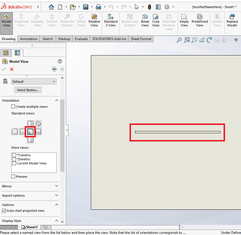
The view we want is the top view, since we want to make a drawing of the part with the text on it. These are things you have to consider when making a drawing and submitting the file to us.
Move the mouse to the desired position you would like the 2D model view to be. Click for the view to appear instead of only an outline.
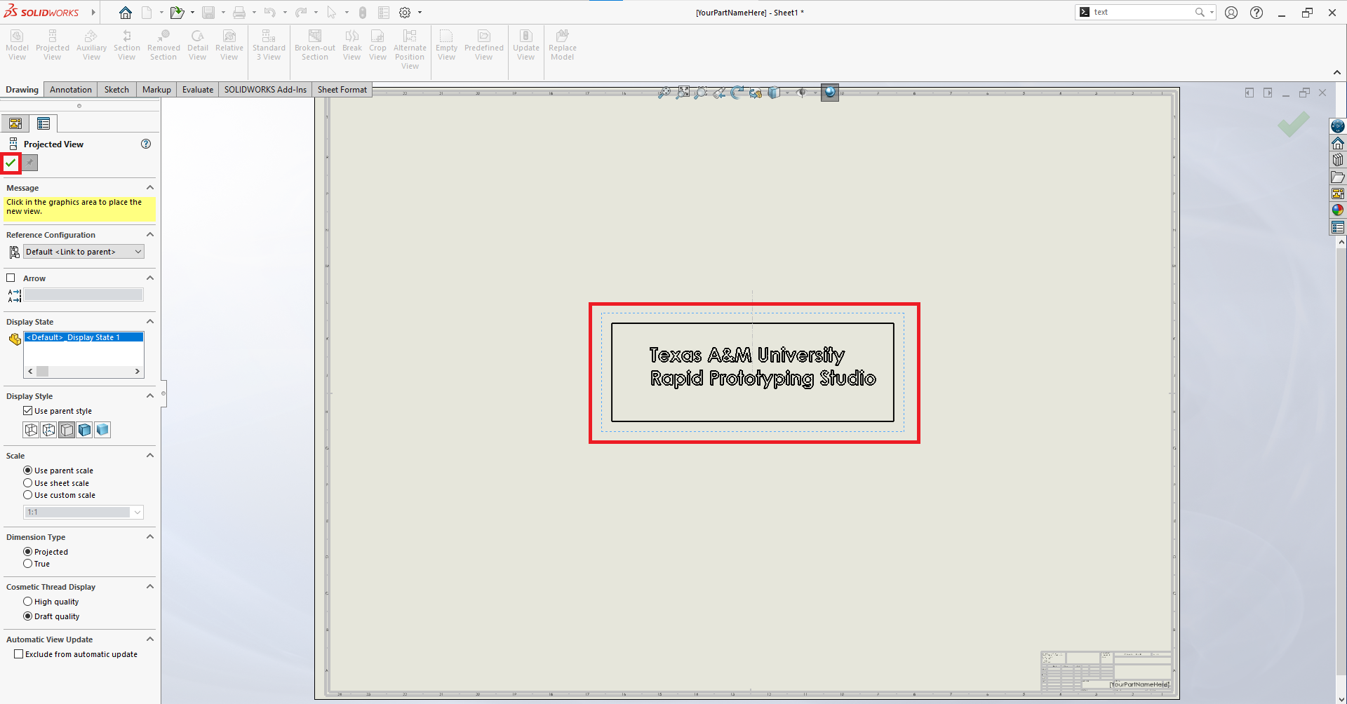
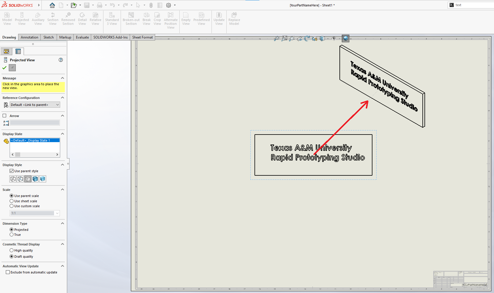
Solidworks will assume you would like to make different views of the part on the same drawing file. This is very typical since engineering drawings typically have several different views. It allows you to represent your 3D geometry across a set of 2D images. Since we want to make a single 2D representation of our part, you do not want several views.
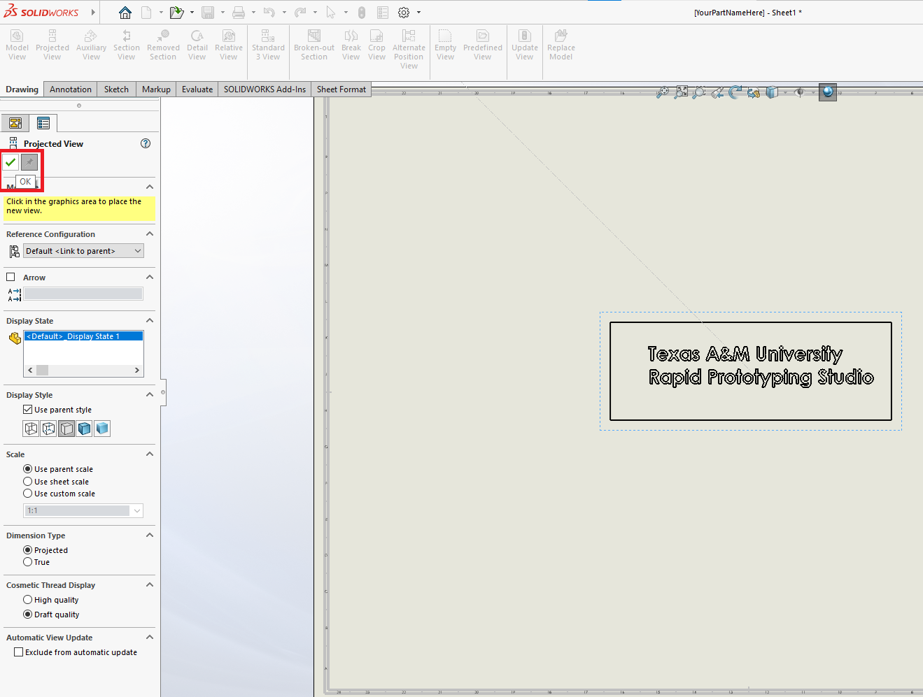
Avoid clicking anywhere on the drawing page plane, and instead go to the left side of the screen and click the green checkbox.
¶ Exporting The File
Hovering over the top left "SOLIDWORKS" text will reveal the standard "file/edit/view/insert/tools/window" ribbon. In the 'File' window, find the 'Save As' ribbon and select.
Save the drawing file as your desired file type. As mentioned before, .dxf files are the most commonly used. Though it depends on what the CAM software you want to use requires.
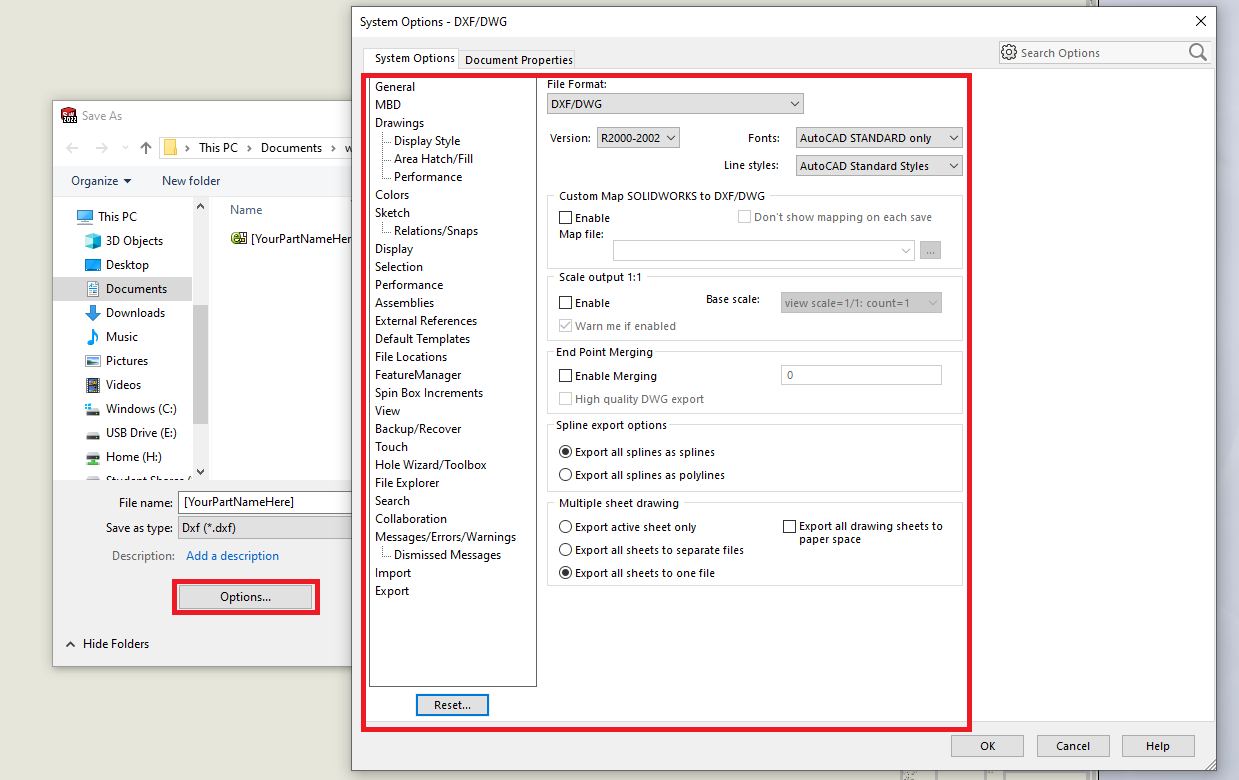
Clicking the 'Options' tab before saving the file will give you a variety of specifics you can make. Generally it is best to leave this alone, but as you get more experienced and have more specific needs for projects, this is a great tool.
¶ Sketching on a Drawing
Another method is to create a sketch on a drawing directly.
¶ Creating The Drawing
When first opening Solidworks you will be prompted with the following screen. Click on the 'Drawing' button.
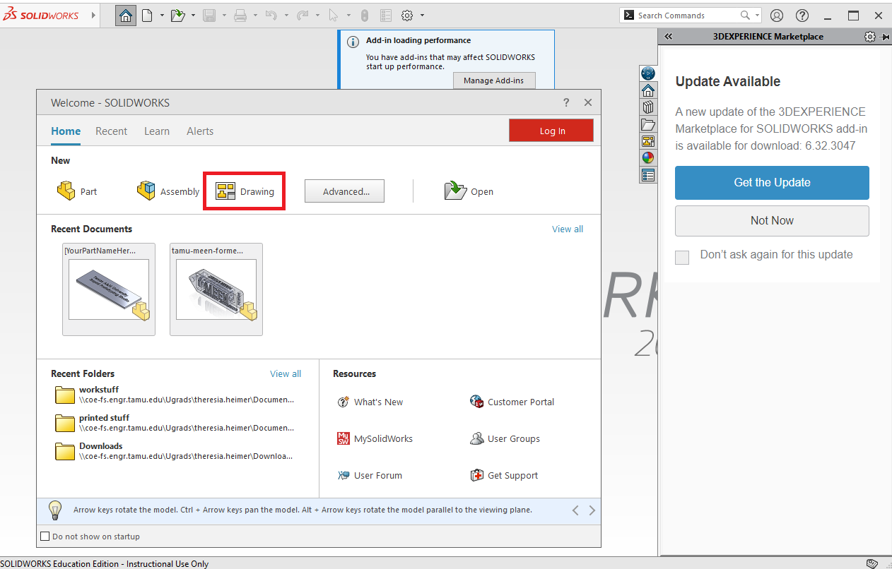
If for some reason, it does not appear, then you can go to the top left and select 'File' and then 'New'.
Now select 'Drawing' and click 'Ok'.
¶ Creating The Sketch
Exit out of the Model View by clicking on the red 'X' that says 'Cancel' while hovering over it.
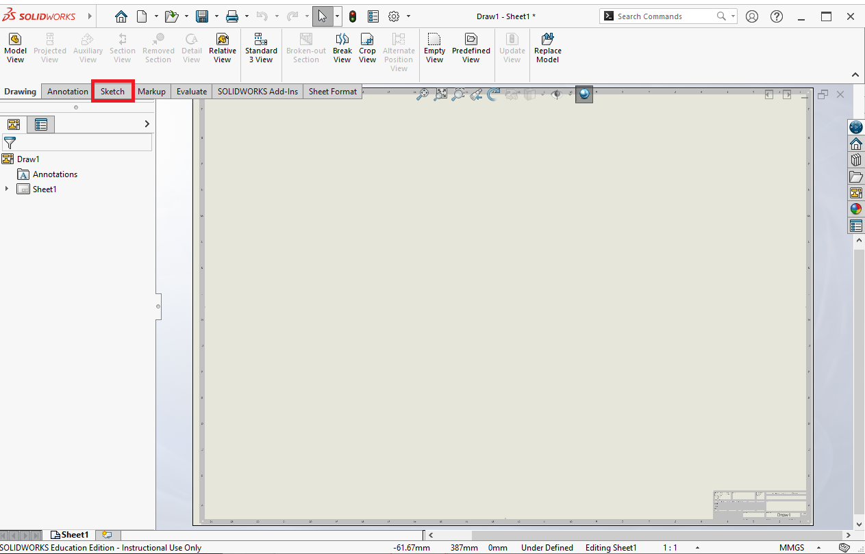
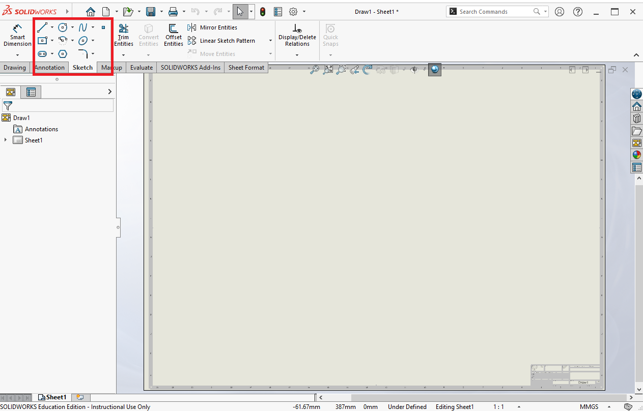
Underneath the main toolbar, you will see that you are on the 'Model' tab. We do not have a model since we are sketching directly on the drawing. Click the 'Sketch' tab.
Now you will be able to create your sketch using the typical sketch tools boxed below. Since this is a guide on how to export a 2D part from Solidworks, this will not cover creating the sketch itself. However, it is idential to creating a sketch normally in a part file.
¶ Notes on Dimensions
When making DXFs for your CAM software you do not normally want to include dimensions. You can include them, but you will have to remove them in the CAM software so that they aren't registered as cuts in your stock. If you don't, the machine will attempt to cut them. The advantage of leaving them on is that it is a reminder to check the size of your import in the CAM software.