¶ Notice for Students:
For this semester (Spring 2025), the plasma cutter will be exclusively operated by RPS staff. This is because we are still working to find and solve any problems with cutting different materials in different situations.
We are also figuring out a way to create some pre-training resources (videos/guides/etc.) so that the process of getting something cut is smoother.
For now, this page is only meant to serve as a base introduction to the plasma cutter, and give students an idea about what to expect. We are NOT training students on the plasma cutter, we are only running parts for people (15 credits/hr)
¶ Things to prepare for cutting reservation
- DXF file
- Ensure that material thickness is within the limits (see table below)
- Make sure that you specify material thickness & type in reservation
¶ Limits & Tolerances
In theory, anything conductive can be cut. Practically, we are only cutting Aluminum as well as mild/stainless steel.
¶ Cut Thickness Limits
| Material | Min (Experimental) | Min (45A) | Max (Piercing, 65A) | Max (Edge Start[1], 65A) |
|---|---|---|---|---|
| Aluminum | 16GA, 30A | 1/8" | 1/2" | 3/4" |
| Mild Steel | 16GA, 30A | 10GA | 5/8" | 3/4" |
| Stainless Steel | 26GA, 20A | 12GA | 1/2" | 1" |
¶ Tolerance
¶ For materials under 1/4" thick, we can generally expect parts to be within 0.05" if settings are applied correctly.
¶ Plasma Cutting is also much faster than the waterjet cutters we have at the RPS
It's hard to give a number for the tolerance of this machine, because of how many factors go into the cut.
- It's not like CNC Machining because the cutting tool is not rigid (plasma is a fluid)
- It's closer to water jet cutting, but the plasma stream does not have the same velocity/pressure as the water stream in a decent waterjet cutter
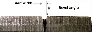
Especially for thicker materials (>3/8"), the plasma stream can be deflected away from the center of the nozzle, causing what is known as a bevel angle. The behavior of this angle is caused by many factors, but the most common of which is incorrect (non-optimal) cut speed. Fixing this issue would require extensive testing & tuning for each thickness/type of material, which will probably not happen soon.
¶ Bevel angle illustration:
Some good questions to ask yourself
- "Am I okay with having to put some work in to make it dimensionally accurate?"
- "For the accuracy I want, would I rather just CNC machine this with a mill/lathe?"
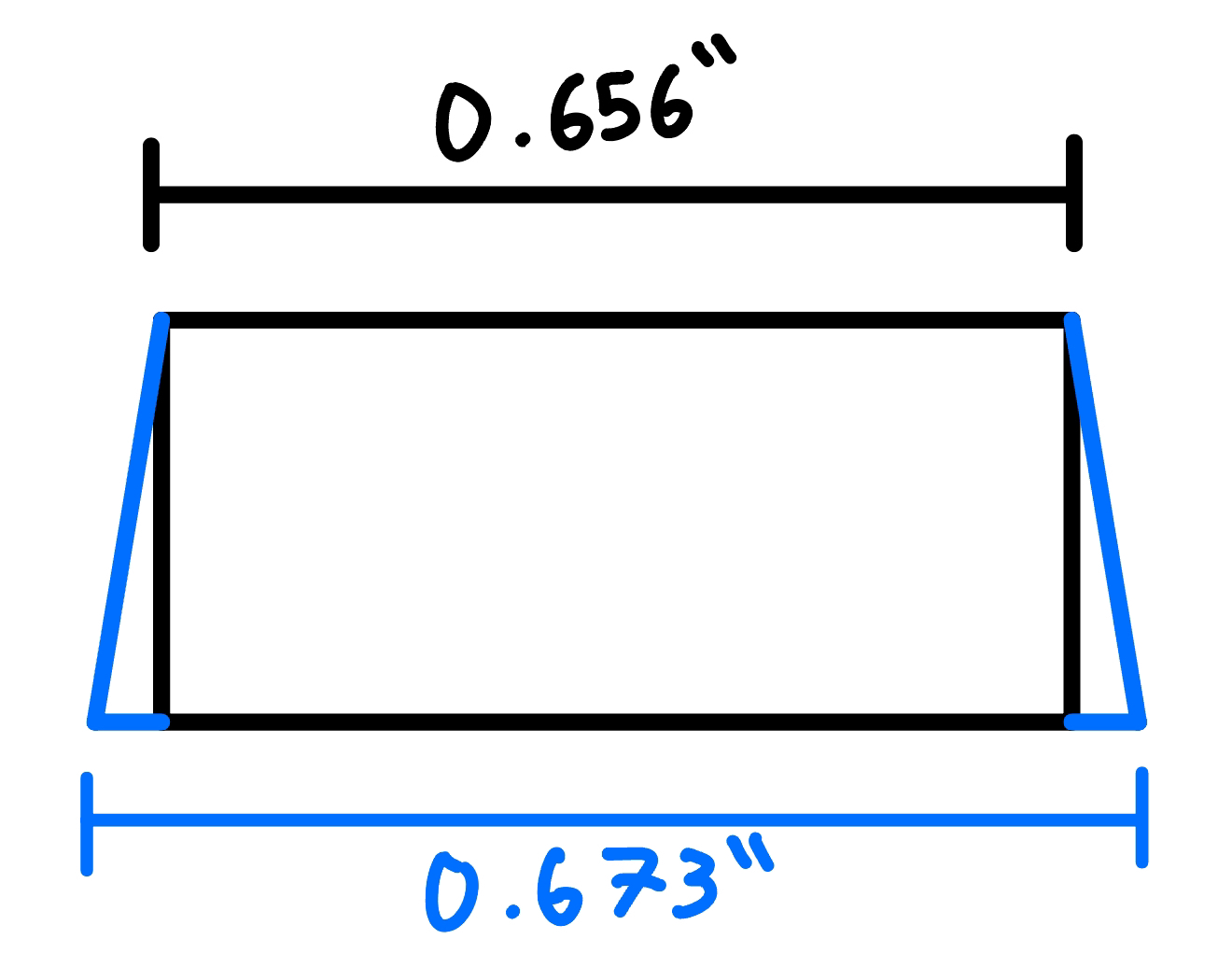
As a rule of thumb, expect the bottom edge of your part to be on the order of 0.020" larger on the bottom due to bevel angle. Shown below is an example of a cut I made from 1/2" Mild Steel for a personal project, but it demonstrates the effect of bevel angle. The top dimension (0.656") is accurate. For the purposes of this project, this angle is fine, but in situations where the sides have to be square, it would be a big pain to correct this issue.
¶ RPS Plasma Cutter
¶ Torchmate 4x4 Growth series Plasma Cutter
Curtain Closed:
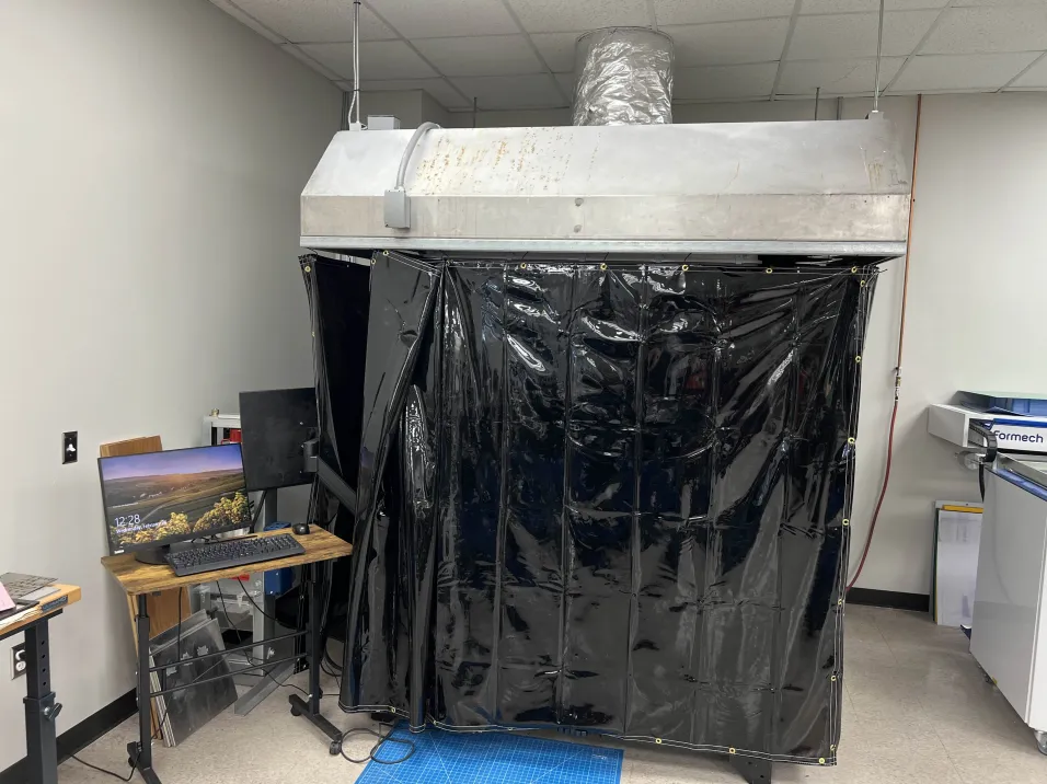
Curtain Open:

- Torchmate growth series Support page for info
- Hypertherm Powermax65 Product page for specs
¶ Post Processing
In short, making a part that looks clean/shiny will require LOTS of post processing effort.
To go more in-depth, the amount of time processing will take will depend on your standards for dimensional accuracy, surface finish, desired heat treatment, etc.
¶ Dimensional Accuracy
As mentioned above, parts that come right off the cutter may not be perfectly square, or perfectly accurate. As such some of the post processing may be dedicated to getting dimensional accuracy, if your part necessitates it
Tools that we have:
- Flap discs
- Cutting Wheels
- Files
- Sand paper of varying grits (60-320)
- Dremel sanding drums (low grit)
- Orbital sander (with 220/320 grit pads)
Tools that we don't have:
- Manual Mill
- Belt or combo sander
- Bandsaw
¶ Surface Finish
Often times, when buying sheets or bars of metal, facilities will store them outside, leading to the stock material becoming dirty, or even rusted. Cleaning up the material can be a hassle, depending on the desired surface quality, and depending on the quality before cutting.
In short, getting a surface to look shiny will sometimes take considerable effort, depending on the tools you have available to you, and the geometry/size of the part. There are many people on youtube, or various forums who give step-by-step tutorials for bringing various metals to a mirror-finish using various tools.
Some standard steps are listed out below as a guide. Everyone has their own philosophies regarding specific steps to take.
¶ Roughing
- Tools: Flap disk, Cutting Wheel, File, <120 grit sandpaper, various power tools for lots of material removal
In this stage, you're just trying to remove slag (dross) from the material, and expose the unoxidized material that is lying under any layers of rust/paint/coatings/etc. You don't really need to be delicate here, as long as you don't completely ruin the part.
You may also have to use the cutting wheel to separate your part from the stock. We are trying to fix this in software, but it still happens sometimes.
¶ Sanding
- Tools: 200-2000 grit sandpaper, orbital sander, sandblaster,
In this stage, the idea is to use progressively higher grit sandpaper to decrease the size of the scratches. This will require
Low grit sandpaper -> large grit particles -> big scratches
High grit sandpaper -> small grit particles -> small scratches
As you go through this stage, you can feel as the part gets smoother and smoother.
¶ Polishing
- Tools: 2000+ grit sandpaper, polishing wheel, dremel (with polishing pads), polishing compound
This is usually the final stage, where soft polishing/buffing wheels are used with abrasive polishing compound to get rid of any remaining micro-scratches to leave a mirror finish. Compounds may sometimes have a 'grit' number, or may just be labeled with 'coarse', 'medium', 'fine', etc.
Generally it's the same idea, where you want to start with the coarsest compound, and work your way up (washing between compound stages).
With whatever machine you choose for this step, be sure to read about how to use it, as going too fast or hard may lead to burning the polishing compound.
¶ Heat Treatment / Holes
As you learned (or will learn) in MEEN 361, some alloys (typically of steel) will harden when heated then rapidly cooled. This happens in processes like welding, as well as for plasma cutting. The system uses pressurized air to force the plasma down, but it also serves to agitate the water below to cool the part (to prevent the entire stock material from melting).
This being the case, if the material is hardenable, you can expect the cut part to come out with material hardening along any of the cuts it made. If you're planning to use the plasma cutter to make drill guides, or you want to CNC machine the material afterward, keep in mind that you'll be dealing with hardened material.
This can be alleviated by annealing the metal (heating it up above the material's recrystallization temperature, then allowing it to cool down slowly). We have a small tabletop furnace that can reach 2200F, but we have never done this before.
If you think that hardened material will be a problem, please talk to one of us in-person, and we can try to come up with some possible solutions.
¶ Plasma Cutting Background
Plasma cutters work by using a jet of ionized air to melt the metal, then blast it into the water bed below. First, air is allowed to flow through the nozzle, then a high frequency AC voltage is applied between the electrode and nozzle (≈15kV, 2MHz) to heat the air to roughly 40,000°F source, which turns it into a plasma. This ionized plasma stream is forced down and out of the nozzle by the air, until it contacts the workpiece.
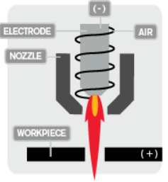
From here, the AC voltage is shut off, and the cutter switches to a DC voltage (≈124-147V) to keep the plasma going. The insanely high air temperature strips air molecules of their electrons, vastly decreasing the electrical resistance of the air. So while many kV are required to start the arc, a much lower voltage (relatively speaking) is required to keep it going.
The two halves of this machine are the plasma power supply, and the torchmate CNC movement system. In this document, the former is often referred to as “Power supply” or “Powermax65,” while the latter is often referred to as “Accumove unit.”
Additionally, there are two main pieces of software required to run this machine. Torchmate CAD/CAM, which comes in EDU-S, and EDU-M versions (Student/Master respectively). The former is free to download on any computer, and can be used to prepare a .edu file, which contains information like toolpaths, tool type, and some material settings.
The master version is only available on ONE computer, which will remain next to the plasma cutter. This version is the same as EDU-S, with the added capability of generating gcode for VMD.
For now, we recommend NOT downloading torchmate EDU-s, and leave the file preparation to the staff running the machine. We are working on possibly using Fusion, or some other modern software to prepare jobs, but this is still a work in progress, and we have no estimate for when this may be done.
The other software, Torchmate Visual Machine Designer (VMD), is used to interface with the physical CNC controller, and is used to run the plasma cutter.
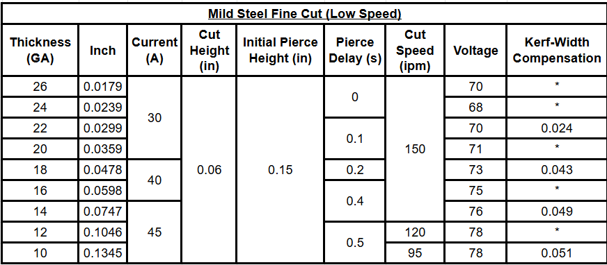
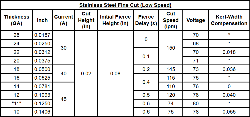
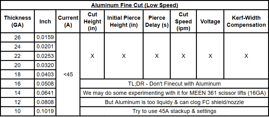
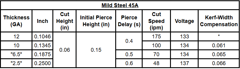
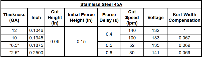
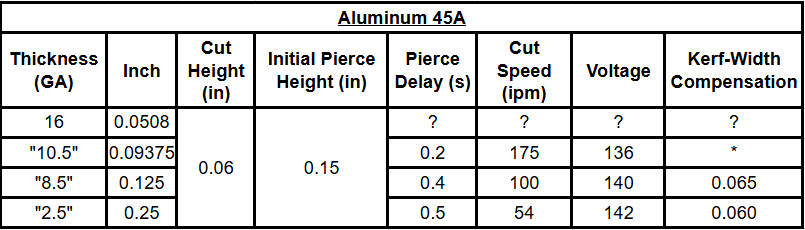
¶ Cut Charts
For cells with an *, this means that Hypertherm does not list the parameter for that thickness. Typically values may be interpolated/extrapolated within reason. If you'd like us to test a specific material thickness, and have some stock to spare, let us know and we can do some testing to find the kerf compensation.
¶ Fine Cut Stackup (<45A)
¶ 45A Stackup
¶ 65A Stackup

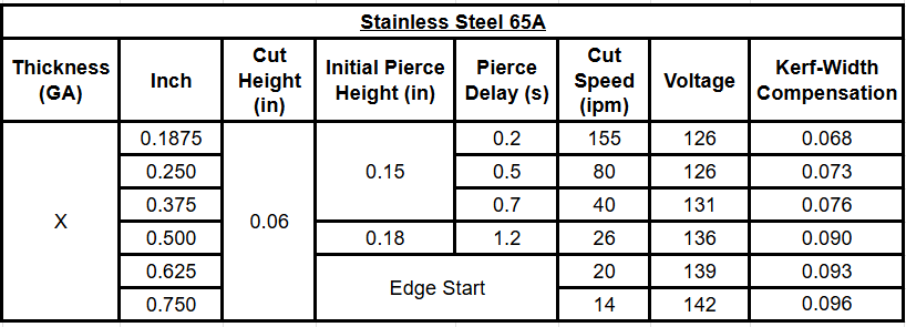
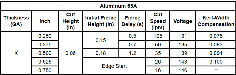
Past a certain thickness, piercing becomes too difficult on the consumables, and can cause faster wear.
This is alleviated by starting a cut on the edge of the material, such that the molten metal is blown down into the water, instead of up back towards the nozzle (which is what happens with piercing). As such, for cutting a material that is thicker than the maximum piercing thickness, any internal geometries become impossible unless a hole is pre-drilled. ↩︎